PERCOBAAN 2
KOMUNIKASI SPI MENGGUNAKAN ARDUINO
1. Rangkai komponen sesuai percobaan dan kondisi yang dipilih.
2. Buat program menggunakan Arduino IDE.
3. Compile program yang telah dibuat lalu Upload ke dalam Arduino Uno.
4. Uji coba program pada rangkaian percobaan sesuai dengan kondisi yang diinginkan.
5. Selesai
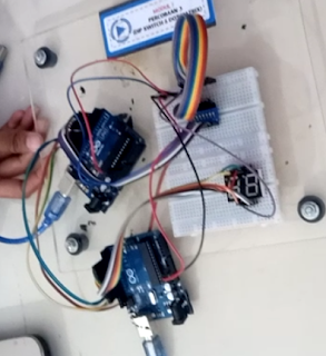
2. Hardware dan Diagram Blok
[Kembali]
Hardware:


3. Rangkaian Simulasi dan Prinsip Kerja
[Kembali]
Rangkaian Simulasi:
Prinsip Kerja:
Setelah program selesai diinputkan ke software arduino, lalu program dijalankan dan diupload ke hardware arduino. Pada percobaan ini menggunakan komunikasi SPI dimana dalam penguploadan kodingan arduino (master & slave) bisa dilakukan dengan bersamaan. Setelah di upload, arduino master akan menerima inputan dari dipswitch dan akan dikirimkan ke arduino slave. Kemudian arduino slave akan menerima sinyal dan outputnya akan ditampilkan di seven segment, yaitu dimana pin berapa saja yang aktif dan nantinya akan ditampilkan pada seven segment.
4. Flowchart dan Listing Program
[Kembali]
Flowchart :

Listing Program :
Master
//Master Arduino
#include<SPI.h> //Library for SPI
int dip[] = {2,3,4,5,6,7,8,9};
int dipvalue[] = {};
void setup (){
Serial.begin(9600); //Starts Serial Communication at Baud Rate 115200
for(int i = 0; i < 8; i++){
pinMode(dip[i], INPUT_PULLUP);
}
SPI.begin(); //Begins the SPI commnuication
SPI.setClockDivider(SPI_CLOCK_DIV8); //Sets clock for SPI communication at 8 (16/8=2Mhz)
digitalWrite(SS,HIGH); // Setting SlaveSelect as HIGH (So master doesnt connnect with
slave)
}
void loop(void){
byte Mastersend;
int x = 1;
for(int i = 0; i < 8; i++){
dipvalue[i] = digitalRead(dip[i]);
if(dipvalue[i] == LOW){
x = dip[i];
}
}
digitalWrite(SS, LOW); //Starts communication with Slave connected to master
Mastersend = x;
Serial.println(Mastersend);
SPI.transfer(Mastersend); //Send the mastersend value to slave also receives value from slave
delay(1000);
}
Slave
#include<SPI.h>
const int segmentPins[] = {9, 8, 7, 6, 5, 4, 3, 2};
volatile boolean received = false;
volatile byte Slavereceived;
int index;
void setup(){
Serial.begin(9600);
for (int i = 0; i < 8; i++) {
pinMode(segmentPins[i], OUTPUT);
}
SPCR |= _BV(SPE); //Turn on SPI in Slave Mode
SPI.attachInterrupt(); //Interuupt ON is set for SPI commnucation
}
ISR (SPI_STC_vect){ //Inerrrput routine function
Slavereceived = SPDR; // Value received from master if store in variable slavereceived
received = true; //Sets received as True
}
void loop(){
Serial.println(Slavereceived);
if(received){//Logic to SET LED ON OR OFF depending upon the value recerived from master
displayCharacter(Slavereceived);
delay(1000);
}
}
void displayCharacter(int ch) {
byte patterns[10][7] = {
{0, 0, 0, 0, 0, 0, 1}, // 0
{1, 0, 0, 1, 1, 1, 1}, // 1
{0, 0, 1, 0, 0, 1, 0}, // 2
{0, 0, 0, 0, 1, 1, 0}, // 3
{1, 0, 0, 1, 1, 0, 0}, // 4
{0, 1, 0, 0, 1, 0, 0}, // 5
{0, 1, 0, 0, 0, 0, 0}, // 6
{0, 0, 0, 1, 1, 1, 1}, // 7
{0, 0, 0, 0, 0, 0, 0}, // 8
{0, 0, 0, 0, 1, 0, 0} // 9
};
if ((ch >= 0 && ch <= 9)) {
// Get the digit index (0-9) from the character
int index = ch;
// Write the pattern to the segment pins
for (int i = 0; i < 7; i++) {
digitalWrite(segmentPins[i], patterns[index][i]);
}
}
}
5. Kondisi [Kembali]
Percobaan 2 pada Modul 3
7. Download File
[Kembali]
Download HTML klik disini
Download Video Percobaan klik disini
Download Listing Program klik disini
Download datasheet arudino klik disini


Tidak ada komentar:
Posting Komentar